Currently internet routing table is growing drastically and every ISP is looking to move ahead over IPv6. But what I think ISP really no needs to migrate the whole backbone over IPv6 because the core doesn’t have more than 5000 – 10000 routes in extreme conditions. Enabling IPV6 simply putting an extra overhead with OSPFv3 and really cumbersome to memorize the schema. So it’s very difficult for operations to troubleshoot the problems with no time.
Customers can use the IPv6 but BGP 6VPE is the best solution to provide the MPLS services or vrf nat also works for same.
Till the time organizations are thinking of rolling out IPv6 services. But after watching LISP video I got feel good factor that Cisco Engineers are doing great job to stop the depletion of increasing routing table. Farinacci along with team has proposed the LISP solution so that the internet routing table could be decrease. Currently internet is having approx 288000 routes and increasing day by day.
LISP stands for LOcator/ID Separation Protocol which will help us to reduce the internet routing table size. But still it is in the deployment phase and everyone is waiting eagerly. As per LISP architecture designers will add a new network layer underneath the network layer, in other terms one can say it’s like encapsulation, legacy of Cisco. Currently every source is having information of every destination consequence internet routing table size increases. Hopefully we will be getting LISP in the coming years.
Full problem statement can be downloaded from here.
regards
shivlu jain
Click Here To Read Rest Of The Post...
Tuesday, March 31, 2009
IP Dialing From PC To LNS and Radius Will Authenticate

This post will cover the ip dialing from Microsoft PC with using PPTP protocol. Once PC is able to dial LNS which is 1.1.1.1 there after radius will authenticate the username and password sent by the PC. Once it is authenticated LNS will allocate the ip address from the pool configured to PC.
How VPDN works
a) PC will dial LNS public ip.
b) A ppp call will come to LNS and it will forward to the radius.
c) Radius will check the credentials and replied back to LNS.
d) There after LNS will allocate the ip address to PC from the Pool configured.
Configuration
Configure Router as LNS
aaa new-model
!
!
aaa group server radius default-group
server-private u.v.w.y auth-port 1645 acct-port 1646 key 7 044F1E0A06314F410
717001406
### Default-group is created and under this radius ip address is given with port number and password. ###
ip radius source-interface loopback0
deadtime 0
!
aaa authentication ppp default group default-group local
#####Default-Group is called here. The command tells whenever ppp packets will come forward it to default-group and if the group is not available then do the local authentication ######
!
vpdn enable ### Command used for enabling VPDN###
!
vpdn-group 1 ### Under this vpdn group virtual template is binding###
! Default PPTP VPDN group
accept-dialin
protocol pptp ###PPTP is the dialing protocol###
virtual-template 1 ###Virtual template 1 is calling here###
local name CE_Router ###Hostname is required and the same is configured in Radius#
!
interface Loopback0
Description For Radius
ip address 2.2.2.2 255.255.255.255
!
interface Loopback226
Description Customer will dial This IP From PC
ip address 1.1.1.1 255.255.255.248
!
interface Virtual-Template5
ip unnumbered loopback226 ###Binding loopback with virtual template###
peer default ip address pool TEST ###After authentication IP will be allocated from TEST Pool ###
ppp authentication pap chap ###Authentication protocol###
!
ip local pool TEST 1.1.1.1 1.1.1.6 ###Local Pool###
Radius Configuration
[ //localhost/Radius/UserLists/shivlujain ]
Name = shivlujain
Description =
Password =
Enabled = TRUE
Group~ =
BaseProfile~ =
AuthenticationScript~ =
AuthorizationScript~ =
UserDefined1 =
AllowNullPassword = FALSE
Attributes/
CheckItems/
Username shivlujain and password cisco is created and the same will be provided during dialing from PC.
Debug Outputs
CE_Router# debug radius
ppp58 PPP: Using vpn set call direction
ppp58 PPP: Treating connection as a callin
ppp58 PPP: Session handle[FB000051] Session id[58]
ppp58 PPP: Authorization required
ppp58 PAP: I AUTH-REQ id 30 len 16 from "shivlujain"
ppp58 PAP: Authenticating peer test2
ppp58 PPP: Sent PAP LOGIN Request
RADIUS/ENCODE(0000004F):Orig. component type = VPDN
RADIUS: AAA Unsupported Attr: interface [157] 14
RADIUS: 55 6E 69 71 2D 53 65 73 73 2D 49 44 [Uniq-Sess-ID]
RADIUS(0000004F): Config NAS IP: 2.2.2.2
RADIUS/ENCODE(0000004F): acct_session_id: 75
RADIUS(0000004F): sending
RADIUS(0000004F): Send Access-Request to u.v.w.y:1645 id 1645/41, len 91
RADIUS: authenticator E8 0E 9B AA 9D FF A2 77 - 57 53 8A E7 CF FA 4B 6B
RADIUS: Framed-Protocol [7] 6 PPP [1]
RADIUS: User-Name [1] 7 "shivlujain"
RADIUS: User-Password [2] 18 *
RADIUS: NAS-Port-Type [61] 6 Virtual [5]
RADIUS: NAS-Port [5] 6 58
RADIUS: NAS-Port-Id [87] 16 "Uniq-Sess-ID58"
RADIUS: Service-Type [6] 6 Framed [2]
RADIUS: NAS-IP-Address [4] 6 2.2.2.2
RADIUS: Received from id 1645/41 u.v.w.y:1645, Access-Accept, len 32
RADIUS: authenticator 2D 38 D5 50 43 DB 31 BE - 1C A4 2F 8E 2F D9 9A 7E
RADIUS: Service-Type [6] 6 Framed [2]
RADIUS: Framed-Protocol [7] 6 PPP [1]
RADIUS(0000004F): Received from id 1645/41
ppp58 PPP: Received LOGIN Response PASS
%LINK-3-UPDOWN: Interface Virtual-Access3, changed state to up
CE_Router#debug ppp authentication
PPP authentication debugging is on
ppp60 PPP: Using vpn set call direction
ppp60 PPP: Treating connection as a callin
ppp60 PPP: Session handle[47000058] Session id[60]
ppp60 PPP: Authorization required
ppp60 PAP: I AUTH-REQ id 31 len 16 from "shivlujain"
ppp60 PAP: Authenticating peer test2
ppp60 PPP: Sent PAP LOGIN Request
ppp60 PPP: Received LOGIN Response PASS
%LINK-3-UPDOWN: Interface Virtual-Access3, changed state to up
Vi3 PPP: Sent LCP AUTHOR Request
Vi3 PPP: Sent MLP AUTHOR Request
Vi3 LCP: Received AAA AUTHOR Response PASS
Vi3 MLP: Received AAA AUTHOR Response PASS
Vi3 PAP: O AUTH-ACK id 31 len 5
%LINK-3-UPDOWN: Interface Virtual-Access4, changed state to up
%LINEPROTO-5-UPDOWN: Line protocol on Interface Virtual-Access3, changed state t
o up
Vi4 PPP: Sent IPCP AUTHOR Request
Vi4 IPCP: Received AAA AUTHOR Response PASS
%LINEPROTO-5-UPDOWN: Line protocol on Interface Virtual-Access4, changed state t
o up
Show Commands
Show users will provide you the list of connected interface.
regards
shivlu jain
Click Here To Read Rest Of The Post...
Monday, March 30, 2009
Untagged Labels Coming Instead Of POP Labels

Problem Description
In the given scenario loopbacks are advertised as /24 subnet. So local router will advertise loopback0 as implicit null to it adjacent neighbours with pop tag but the adjacent routers are receiving Untagged entries.
For simplicity I am using R1 to capture all the outputs. In the given outputs I am verifying loopback 0 of router 3.
FIB of R1
R1#sh mpls forwarding-tableLocal Outgoing Prefix Bytes tag Outgoing Next Hop
tag tag or VC or Tunnel Id switched interface
18 Untagged 172.16.3.3/32 0 Fa0/0 10.1.1.1
19 Untagged 172.16.2.2/32 0 Fa0/1 10.1.2.2
FIB of R1
R1#show mpls forwarding-tableLocal Outgoing Prefix Bytes tag Outgoing Next Hop
tag tag or VC or Tunnel Id switched interface
18 Untagged 172.16.3.3/32 0 Fa0/0 10.1.1.1
19 Untagged 172.16.2.2/32 0 Fa0/1 10.1.2.2
The loopbacks are advertised as /24 subnet mask and adjacent routers are receiving /32 entry in the routing table because by default loopbacks interface in ospf treated as stub host.
R3# sh ip ospf interface loopback 0
Loopback0 is up, line protocol is up
Internet Address 172.16.3.3/24, Area 0
Process ID 1, Router ID 172.16.3.3, Network Type LOOPBACK, Cost: 1
Enabled by interface config, including secondary ip addresses
Loopback interface is treated as a stub Host
Now if you check the adjacent router routing table loopback entry will come as /32 but it advertise the loopback (172.16.3.3/24) as implicit null. Now check the routing table entry of 172.16.3.3 and mpls binding in R1.
R1#Show ip route 172.16.0.0/16 is variably subnetted, 3 subnets, 2 masks
O 172.16.3.3/32 [110/2] via 10.1.1.1, 03:15:04, FastEthernet0/0
O 172.16.2.2/32 [110/2] via 10.1.2.2, 03:14:54, FastEthernet0/1
C 172.16.1.0/24 is directly connected, Loopback0
10.0.0.0/30 is subnetted, 2 subnets
C 10.1.2.0 is directly connected, FastEthernet0/1
C 10.1.1.0 is directly connected, FastEthernet0/0
Show mpls ldp binding of R1tib entry: 172.16.3.0/24, rev 34(no route)
remote binding: tsr: 172.16.3.3:0, tag: imp-null
tib entry: 172.16.3.3/32, rev 31
local binding: tag: 18
remote binding: tsr: 10.1.2.2:0, tag: 20
Show mpls forwarding of R1
R1#sh mpls forwarding-table
Local Outgoing Prefix Bytes tag Outgoing Next Hop
tag tag or VC or Tunnel Id switched interface
18 Untagged 172.16.3.3/32 0 Fa0/0 10.1.1.1
19 Untagged 172.16.2.2/32 0 Fa0/1 10.1.2.2
See carefully the output tag of 17216.3.3/32 which is Untagged. Instead of Untagged it should be pop label.
POP Label:- The router before the last LSR (the penultimate hop) pops the label and transmits the packet without the label. The last hop is called the egress LSR.
Untagged Label:- Untagged label in the LFIB when the IP prefix is a directly connected interface, a summary route or the next-hop router has not advertised the label.
You can see the “The next hop router has not advertised the label”. The next router is advertising implicit null for /24 but routing table doesn’t have any entry for the same.
Solution:- The same type of problem I faced during my CCIE lab exam. It was supposed to advertise the loopback with the exact subnet but we usually get the entry as /32. So remember this command which will resolve the whole issue.
Command is “ip ospf network point-to-point” under loopback0.
Now check the routing table, mpls binding and forwarding table of R1
Routing Table
172.16.0.0/24 is subnetted, 3 subnets
C 172.16.1.0 is directly connected, Loopback0
O 172.16.2.0 [110/2] via 10.1.2.2, 00:00:52, FastEthernet0/1
O 172.16.3.0 [110/2] via 10.1.1.1, 00:00:42, FastEthernet0/0
10.0.0.0/30 is subnetted, 2 subnets
C 10.1.2.0 is directly connected, FastEthernet0/1
C 10.1.1.0 is directly connected, FastEthernet0/0
Forwarding Table
R1#sh mpls forwarding-table
Local Outgoing Prefix Bytes tag Outgoing Next Hop
tag tag or VC or Tunnel Id switched interface
16 Pop tag 172.16.2.0/24 0 Fa0/1 10.1.2.2
17 Pop tag 172.16.3.0/24 0 Fa0/0 10.1.1.1
Here you got the Pop tag. (Pop tag is already explained)
LDP Binding Table
tib entry: 172.16.1.0/24, rev 6
local binding: tag: imp-null
remote binding: tsr: 172.16.3.3:0, tag: 18
remote binding: tsr: 10.1.2.2:0, tag: 16
Click here to download the full document.
regards
shivlu jain (TULIP)
Click Here To Read Rest Of The Post...
Saturday, March 28, 2009
Ip Dialing From PC To LNS
Every enterpries needs a remote access during roaming and vpnd is the best solution which can be used witout installing software on microsoft windows. This type of solutionis also known as ip dialing. For remote access laptop/pc should be connected to internet and able to reach the global internet ip address. If this option is available then its very easy to deploy the solution. I have tested it on a simple scenarion in which PC is connected via DSL and using simple PPTP(Point To Point Tunneling Protocol) to dial the public enterprise ip address.
Topology
PC----DSL-----------Internet---------EnterpriseHO---------Enterprise Network
In the above topolgy Enterprise HO router is enabled with VPDN(Virtual Dialup Network) so that it can work as LNS(Layer2 Nework Server). Now Remote PC will dial LNS public ip adress and after successfull authetication remote PC will be allocated with a public ip address and able to access its lan routers.
Authentication is done locally from router itself.
Configuration
int loopback 100
!Ip which is reahable from internet and remote PC will dial it
ip address 20.225.22.1 255.255.255.248
vpdn enable
vpdn-group 1
! Default PPTP VPDN group
accept-dialin
protocol pptp
virtual-template 5
local name CE_Router
interface Virtual-Template5
ip unnumbered Loopback100
peer default ip address pool TEST1
ppp authentication pap chap
ppp multilink
ip local pool TEST1 20.235.22.2 20.235.22.6
Explanation of each command
Vpdn enable - This command is used to make router as LNS.
accept-dialin - This command is used to accept dial services.
protocol pptp - This command is used to accept protocol as pptp during dialing which is used by microsoft PC.
virtual-template 5 - This command is used to bind virtual template 5 with vpdn-group1 becasue after dialing virtual access interface will come up.
local name - Host name will be used here.
ip local pool TEST1 - A pool with ip addresses as configured. It means only 5 persons can dial and able to access the lan from outer cloud.
Virtual template
peer default ip address pool TEST1 - Afer successful authentication ip address will be given form pool TEST1
ppp authentication pap chap - This command is used for autheication.
regards
shivlu jain
Click Here To Read Rest Of The Post...
Friday, March 27, 2009
Sparse Mode Made Clients Down
Yesterday during multicast testing we enabled pim on lan interface of cisco router as well as on serial interfaces. In the lab end to end customers were working over l2tpv3 and tunnel was establishing successfully. The moment pim sparse mode was enabled on lan interface end to end customer was not able to reach. But if the customer was conifgured as layer vpn it worked fine end to end. In layer 2 circuit l2tunnel was up but no data flow works on it. As soon as pim sparse mode was disabled from lan interface data flow started on l2 tunnel. Issues faced only with l2tpv3 protocol after enabling pim sparse mode on lan interface.
Cisco IOS used during testing:- c1841-spservicesk9-mz.123-14.YT1.bin
regards
shivlu jain
Click Here To Read Rest Of The Post...
Cisco IOS used during testing:- c1841-spservicesk9-mz.123-14.YT1.bin
regards
shivlu jain
Click Here To Read Rest Of The Post...
Thursday, March 26, 2009
MTI(Multicast Tunnel Interface) is Coming Up But Not Pim Neighborship
Yesterday I got a query on MVPN:-
In MVPN MTI(Multicast Tunnel Interface) is coming up but but end to end pim neighborship on MTI tunnel is not coming up. What is reason for this and how this can be possible?
The question is very intectually. Actually the formation of MTI depends on the default MDT group which is being mentioned under vrf. So once the reachability of that group available in the MPLSVPN cloud MTI tunnel comes up. But PIM neighborship depends on the pim sparse-dense-mode or sparse-mode and if it is not coming up definately in the path pim sparse-dense mode or sparse mode is missing.
regards
shivlu jain
Click Here To Read Rest Of The Post...
Wednesday, March 25, 2009
Pim Vrf Neighborship Not Coming Up In SSM
If the mplsvpn backbone is running over dense mode and serving mvpn services and designers want to migrate the dense mode to ssm. But the mplsvpn core is using type 2 rd which is actually reserve for inter-as mvpn and some of the core routers are running over SB or SRC series ios. During the migration of core; one should not face any type of issue but of mvpwhen migration n customers will start you might face a problem of pim neighborship of vrf not coming up but mdt tunnels up. The main reason for this is that mdt-safi which I have already covered in my previous post. In these cases, ipv4 mdt need to be activated with RR. As soon as it will be configured you will be glad to see mvpn vrf pim neighborships come up.
regards
shivlu jain
Click Here To Read Rest Of The Post...
regards
shivlu jain
Click Here To Read Rest Of The Post...
Tuesday, March 24, 2009
Problems Faced During NTP Deployment
During the implementation of NTP we faced lot of issues. I am covering almost all the issues which will be useful for others during its deployment except stratum because you will find lot of information about stratum. The main purpose of writing this document is that I have never seen any of the documents available on internet which describes the issues.
a) Whenever any of the router works as NTP master by default 127.127.7.1 address comes. So care should be taken while securing NTP with acl to permit this ip address. This address is useful for the peer synchronization.
Router# show ntp associations
address ref clock st when poll reach delay offset disp
*~127.127.7.1 127.127.7.1 7 27 64 377 0.0 0.00 0.0
* master (synced), # master (unsynced), + selected, - candidate, ~ configured
b) While using access-list for peer always permit 127.127.7.1 address in the acl. By mistake if it left both the peers will never sync with each other.
Router# ntp access-group peer 1
Router# access-list 1 permit 10.10.10.40 0.0.0.0
Router# ntp peer 10.10.10.40
Router# show ntp associations
address ref clock st when poll reach delay offset disp
*~10.10.10.10 127.127.7.1 8 58 64 37 424.0 -287.6 937.9
~10.10.10.40 10.10.10.10 9 1 64 6 128.0 -402.8 8128.1
* master (synced), # master (unsynced), + selected, - candidate, ~ configured
If you are getting only tilt(~); it means there might be some problem in the acl or 127.127.7.1 is not permitting in acl. Check your acl and configs. As soon as you add 127.127.7.1 output will be changed.
Note:- NTP doesn’t support named acl. Whatever ip address is defining in peer acl should be manual added with peer command also else it won’t work except 127.127.7.1.
Router# show ntp associations
address ref clock st when poll reach delay offset disp
*~10.10.10.10 127.127.7.1 8 58 64 37 424.0 -287.6 937.9
+~10.10.10.40 10.10.10.10 9 1 64 6 128.0 -402.8 8128.1
* master (synced), # master (unsynced), + selected, - candidate, ~ configured
c) Slow synchronization
Being a slow protocol, at times clock doesn’t update. For that need to remove the configs and add them again.
d) NTP doesn’t support authentication for clients.
regards
shivlu jain
Click Here To Read Rest Of The Post...
Monday, March 23, 2009
NTP Implementation In Service Provider Network

This post will cover how to implement NTP in service provider network. The document will be used as reference for enterprise and corporate networks also.
In the given figure two routers which are 7600 are used as client who is getting NTP clock from the global servers. The same clock is being distributed to the downstream GSR routers. Thereafter GSR are distributing clock to the downstream tier 2 routers. This is the hierarchical implementation of NTP. In fact implementation of NTP is really a awesome job if you are having patience.
How NTP flow will work
7600 routers are getting global NTP clock of stratum 0 from global servers. List of global server is given below. Once the clock is received by 7600; both will work as master for the downstream GSR routers. Now GSRs will receive clock from 7600 as client and distribute the same clock to the downstream tier 2 routers. For sending the clock GSR will act as server for tier2 routers and client for 7600. Now tier2 routers will receive the clock from GSR as client and distribute the same clock to the downstream tier2 routers. For this we need to implement tier2 routers as servers for downstream routers and client for GSRs.
Security
Access-list is used for security purpose because once the routers will become as server; internet cloud can use the same routers as reference clock.
List of free servers
Philippines ph.pool.ntp.org
Malaysia my.pool.ntp.org
Turkey tr.pool.ntp.org
Singapore sg.pool.ntp.org
India in.pool.ntp.org
Hong Kong hk.pool.ntp.org
Japan jp.pool.ntp.org
Bangladesh bd.pool.ntp.org
Israel il.pool.ntp.org
Korea kr.pool.ntp.org
Thailand th.pool.ntp.org
Iran ir.pool.ntp.org
Taiwan tw.pool.ntp.org
China cn.pool.ntp.org
Indonesia id.pool.ntp.org
Vietnam vn.pool.ntp.org
Pakistan pk.pool.ntp.org
Oman om.pool.ntp.org
Configuration
On 7600 [Both 7600 will act as server as well as client]
Clock timezone GMT +5 30
Ntp server in.pool.ntp.org
Ntp server sg.pool.ntp.org
Ntp master 2 ---------- This command is used for creating 7600 as server
Ntp access-group peer 2
ntp access-group serve-only 1
Access-list 1 permit
Access-list 1 permit
Access-list 2 permit <7600 loopback> 0.0.0.0
Access-list 2 permit 127.127.7.1 0.0.0.0
On GSR
Clock timezone GMT +5 30
Ntp server <7600 loopback>
Ntp server <7600 loopback>
Ntp master 3
Ntp access-group peer 2
ntp access-group serve-only 1
Access-list 2 permit
Access-list 2 permit 127.127.7.1 0.0.0.0
Access-list 1 permit
On Tier2
Clock timezone GMT +5 30
Ntp server 172.29.255.254
Ntp server 172.30.255.254
Ntp master 4
Tier 2 Downstream Routers
Clock timezone GMT +5 30
Ntp server
Note:- 127.127.7.1 is used for synchronization of clock between the servers in case of failure on global NTP server.
Verfification
Show ntp associations
Show ntp status
Show ntp clock
regards
shivlu jain
Click Here To Read Rest Of The Post...
Friday, March 20, 2009
Most Commonly RFC
IP
RFC 791, Internet Protocol
RFC 1349, Type of Service in the Internet Protocol Suite
RFC 1812, Requirements for IP Version 4 Routers
RFC 2460, Internet Protocol, Version 6 (IPv6) Specification
IntServ
RFC 1633, Integrated Service in the Internet Architecture: an Overview
RFC 2210, The Use of RSVP with IETF Integrated Services
RFC 2211, Specification of the Controlled-Load Network Element Service
RFC 2212, Specification of Guaranteed Quality of Service
RFC 2215, General Characterization Parameters for Integrated Service Network Elements
RFC 2216, Network Element Service Specification Template
Diff Serv
RFC 2474, Definition of the Differentiated Services Field (DS Field) in the IPv4 and IPv6 Headers
RFC 2475, An Architecture for Differentiated Services
RFC 2597, Assured Forwarding PHB Group
RFC 2697, A Single Rate Three Color Marker.txt
RFC 2698, A Two Rate Three Color Marker
RFC 2983, Differentiated Services and Tunnels
RFC 3246, An Expedited Forwarding PHB (Per-Hop Behavior)
RFC 3247, Supplemental Information for the New Definition of the EF PHB (Expedited Forwarding Per-Hop Behavior)
RFC 3260, New Terminology and Clarifications for DiffServ
RFC 3270, Multi-Protocol Label Switching (MPLS) Support of Differentiated Services
Traffic Management
RFC 2309, Recommendations on Queue Management and Congestion Avoidance in the Internet
RFC 3168, The Addition of Explicit Congestion Notification (ECN) to IP
Shreedhar M. and Varghese G. , "Efficient Fair Queuing Using deficit Round-Robin,"
MPLS
RFC 3032, MPLS Label Stack Encoding
RSVP
draft-ietf-tsvwg-rsvp-dste-01 - RSVP Aggregation over MPLS TE tunnels (work in progress)
draft-ietf-avt-hc-over-mpls-protocol-04-Protocol Extensions for Header Compression over MPLS (work in progress)
RFC 2209, Resource ReSerVation Protocol (RSVP) -- Version 1 Message Processing Rules
RFC 2747, RSVP Cryptographic Authentication
RFC 2961, RSVP Refresh Overhead Reduction Extensions
RFC 2996, Format of the RSVP DCLASS Object
RFC 3097, RSVP Cryptographic Authentication -- Updated Message Type Value
RFC 3175, Aggregation of RSVP for IPv4 and IPv6 Reservations
regards
shivlu jain
Click Here To Read Rest Of The Post...
Thursday, March 19, 2009
Check Your Website Ranking
Alexa is a free web tool which tell us about the web ranking of our blogs, websites and many many more.
For more click here
regards
shivlu jain
Click Here To Read Rest Of The Post...
For more click here
regards
shivlu jain
Click Here To Read Rest Of The Post...
Wednesday, March 18, 2009
Physical Interface Down On Deletion Of Subinterface
Yesterday when logival interface of NPE-G2 router was deleted, at the same instant physical interface got down. The ios which was using 12.2 31 SB13.
regards
shivlu jain
Click Here To Read Rest Of The Post...
regards
shivlu jain
Click Here To Read Rest Of The Post...
Tuesday, March 17, 2009
Walk The Tech Walk
As part of our third quarter communication package, we are delighted to announce that Cisco will be presenting, Walk the Tech Talk series on NDTV Profit, to be anchored by Rajiv Makhni, the well known NDTV technology expert. The first of the 6 part series will be aired tomorrow, Saturday, 28th February and will feature Mr. Laxman Badiga, CIO, Wipro Technologies, as the first guest.
The first five episodes will feature one-on-one interviews with 5 of our key customers and shall demonstrate how Cisco’s collaboration technologies are providing each of them with operational efficiencies and a much needed competitive edge especially during these difficult times. The final episode will be a first-of-its-kind on Indian television, where a panel discussion will happen over Cisco TelePresence, featuring all the five CIOs/CTOs interviewed earlier. NDTV Profit will telecast the series every week at 8:30 p.m. on Saturdays with a repeat show on the following Sunday at 12:30 p.m.
The telecast details of Walk the Tech Talk series are as follows:
Episode 1: Mr. Laxman Badiga, CIO, Wipro Technologies
Telecast: 28 February 2009 8:30pm, Repeat: 01 March 2009, 12:30pm
Technologies to be discussed: TelePresence, Desktop Video Conferencing and Webex
Episode 2: Mr. Ramesh Lakshminarayanan, Group Head – IT Infrastructure, Kotak Bank
Telecast: 07 March 2009 8:30pm, Repeat: 08 March 2009, 12:30pm
Technologies to be discussed: Data Center and Unified Communication
Episode 3: Mr. Jayasimha Varadarajan, VP - IT, Thomson Reuters
Telecast: 14 March 2009 8:30pm, Repeat: 15 March 2009, 12:30pm
Technologies to be discussed: Virtual Switching, Unified Communication and CS Mars
Episode 4: Mr. Umesh Jain, CIO, Yes Bank
Telecast: 21 March 2009 8:30pm, Repeat: 22 March 2009, 12:30pm
Technologies to be discussed: IP Contact Center and Unified Communication
Episode 5: Mr. K. Muralikrishna, SVP, Head - Computers and Communication Division, Infosys
Telecast: 28 March 2009 8:30pm, Repeat: 29 March 2009, 12:30pm
Technologies to be discussed: Unified Communication
Episode 6: Concluding Panel Discussion over Cisco TelePresence
Telecast: 04 April 2009 8:30pm, Repeat: 05 April 2009, 12:30pm
Don’t miss this special series on NDTV Profit – as this will be a true showcase of how Cisco technologies enable the Human Network.
regards
shivlu jain
Click Here To Read Rest Of The Post...
Monday, March 16, 2009
Internet VRF Leaking Bug Declared
From the last one month we are looking for a internet vrf leaking solution in SB13 ios but today finally cisco declared it as a new bug CSCsy29604 which is hampering SRC and SB series.
regards
shivlu jain
Click Here To Read Rest Of The Post...
regards
shivlu jain
Click Here To Read Rest Of The Post...
Friday, March 13, 2009
How to set DF bit from Windows Vista
In the last post we have seen how to check the mtu on windows vista. In this post we will see how to set the DF big on a packet.
On command prompt ping yahoo.com -f -l 1460; you will see the reply. Now ping yahoo with 1500 bytes, you receive packets need to be fragmented. -f is used for donot fragment.
Pinging yahoo.com [206.190.60.37] with 1500 bytes of data:
Packet needs to be fragmented but DF set.
Packet needs to be fragmented but DF set.
Packet needs to be fragmented but DF set.
Packet needs to be fragmented but DF set.
Packet needs to be fragmented but DF set.
Packet needs to be fragmented but DF set.
Packet needs to be fragmented but DF set.
Packet needs to be fragmented but DF set.
Packet needs to be fragmented but DF set.
Packet needs to be fragmented but DF set.
regards
shivlu jain
Click Here To Read Rest Of The Post...
Wednesday, March 11, 2009
How to Check MTU on Windows Vista
MTU is one of the problems which is being faced by everyone when the media is ethernet. But in this post I am not going to tell you about the problems faced with MTU. Simply I wanna show a very simple command in vista which can help you to check the mtu size of your windows.
C:\>netsh interface ipv4 show interfaces
Idx Met MTU State Name
--- --- ----- ----------- -------------------
1 4275 4294967295 connected Loopback Pseudo-Interface 1
9 4230 1500 disconnected Wireless Network Connection 2
21 50 1500 connected Dial-up Connection
8 4230 1500 disconnected Local Area Connection
regards
shivlu jain
Click Here To Read Rest Of The Post...
Tuesday, March 10, 2009
Provisioning Internet With INTERNET vrf
Download the full article
In this post I have covered how to provision Internet to customer if service provider is having the MPLSVPN backbone and the customer is looking for internet as well as vpn services.
R0 – CPE router
R1 – PE router
R2 – Internet Gateway of SP and default route is originating in OSPF
Figure is given below:-
Internet Cloud----------R2----------------R1----------------CE
R2 router is having a directly connected interface with upstream service provider router. A vrf INTERNET is configured on R2 with default route pointing towards the 2.2.2.2 which is available in global routing table. For achieving this global keyword is used. Click here for more information about global keyword in VRF.
Configuration of R2
ip vrf INTERNET
rd 1:2
route-target export 1:2
router bgp 1
address-family ipv4 vrf INTERNET
redistribute connected
no auto-summary
no synchronization
Now check the route table of VRF INTERNET on R2
R2#show ip route vrf INTERNET
Gateway of last resort is 2.2.2.2 to network 0.0.0.0
S* 0.0.0.0/0 [1/0] via 2.2.2.2
BGP routing table for vrf INTERNET
Router#sh ip bgp vpnv4 vrf INTERNET
From the above output of bgp routing table of VPNv4, no default route is coming in the gp routing table. The reason for this is that 2.2.2.2 is not available in vrf INTERNET routing table that’s why it is not installing in the vrf INTERNET bgp routing table. For its completion you need to add a 0.0.0.0 network under address-family INTERNET.
router bgp 1
address-family ipv4 vrf INTERNET
redistribute connected
network 0.0.0.0
no auto-summary
no synchronization
Check the vpnv4 bgp routing table of vrf INTERNET
R2#show ip bgp vpnv4 vrf INTERNET
Network Next Hop Metric LocPrf Weight Path
Route Distinguisher: 1:2 (default for vrf INTERNET)
*> 0.0.0.0 2.2.2.2 0 32768 i
Hurrah! Received default route in bgp routing table of vrf INTERNET.
Being MPLS is enabled in the whole cloud and need to check the label for route in vrf INTERNET. I love utmost the given commands because it gives the full information about the labels. 18 label is generating for given route and r2 will advertise the same route towards the cloud to RR or other PE routers.
R2#show ip bgp vpnv4 vrf INTERNET 0.0.0.0
BGP routing table entry for 1:2:0.0.0.0/0, version 3
Paths: (1 available, best #1, table INTERNET)
Advertised to update-groups:
1
Local
2.2.2.2 from 0.0.0.0 (10.10.10.10)
Origin IGP, metric 0, localpref 100, weight 32768, valid, sourced, local, best
Extended Community: RT:1:2
mpls labels in/out 18/nolabel
R2#show mpls forwarding-table labels 18
Local Outgoing Prefix Bytes Label Outgoing Next Hop
Label Label or VC or Tunnel Id Switched interface
18 No Label 0.0.0.0/0[V] 570 Fa0/1 2.2.2.2
Configure R1 and customer vrf named CUST is coming on same pop. In my previous article of “How Internet Works In MPLS” depicts that a vrf route leaked in global. But in this article CUST vrf requires the default route to access internet freely.
Configuration of VRF CUST on R1
R1#show running-config | section vrf CUST
ip vrf CUST
rd 1:1
route-target export 1:1
route-target import 1:1
router bgp 1
address-family ipv4 vrf CUST
redistribute connected
redistribute static
no auto-summary
no synchronization
Routing table of vrf CUST
Router#sh ip route vrf CUST
Routing Table: CUST
192.168.1.0/30 is subnetted, 1 subnets
C 192.168.1.0 is directly connected, FastEthernet0/1
BGP vpnv4 routing table of vrf CUST
R1#show ip bgp vpnv4 vrf CUST
Network Next Hop Metric LocPrf Weight Path
Route Distinguisher: 1:1 (default for vrf CUST)
*> 192.168.1.0/30 0.0.0.0 0 32768 ?
Till now CUST vrf doesn’t have the default route. For that we need to play with route target. INTERNET vrf is exporting 1:2; in other words one can understand the INTERNET is saying to MPLS cloud those who want to surf internet, accept me. Now CUST vrf wants to surf internet; for this it needs to import that default route in its vrf by using route target import 1:2 in its vrf CUST.
ip vrf CUST
rd 1:1
route-target export 1:1
route-target import 1:1
route-target import 1:2
Routing table of vrf CUST
Router#show ip route vrf CUST
Routing Table: CUST
192.168.1.0/30 is subnetted, 1 subnets
C 192.168.1.0 is directly connected, FastEthernet0/1
B* 0.0.0.0/0 [200/0] via 10.10.10.10, 00:50:36
BGP vpnv4 routing table of vrf CUST
Router#sh ip bgp vpnv4 vrf CUST
Network Next Hop Metric LocPrf Weight Path
Route Distinguisher: 1:1 (default for vrf CUST)
*>i0.0.0.0 10.10.10.10 0 100 0 i
*> 192.168.1.0/30 0.0.0.0 0 32768 ?
From the above output vrf CUST is receiving a default route with next hop 10.10.10.10 which is the router id of R2. R1 will forward the vpnv4 traffic to R1 there after traffic will leak to the global routing table. [Check How internet works in MPLS]
You are amazed because I have been using vpnv4 keyword in the above paragraph. VPNv4 means label will be pushed from R1 to R2 then R2 will remove the label and forward the ip traffic. As per process two labels should imposed on packet; one label for vpnv4 and another label for IGP. But in my scenario R2 is the directly connected router so that implicit null generated for 10.10.10.10 and vpnv4 label of 18 is imposed. This is the same label which is shown in above output of INTERNET vrf. The foremost difference is that in INTERNET vrf label is “in” and on R2 it is showing as “out”.
Router#sh ip bgp vpnv4 vrf CUST 0.0.0.0
BGP routing table entry for 1:1:0.0.0.0/0, version 9
Paths: (1 available, best #1, table CUST)
Not advertised to any peer
Local, imported path from 1:2:0.0.0.0/0
10.10.10.10 (metric 2) from 10.10.10.10 (10.10.10.10)
Origin IGP, metric 0, localpref 100, valid, internal, best
Extended Community: RT:1:2
mpls labels in/out nolabel/18
Router#sh mpls ldp bindings 10.10.10.10 32
lib entry: 10.10.10.10/32, rev 8
local binding: label: 17
remote binding: lsr: 10.10.10.10:0, label: imp-null
For reverse traffic global route is added in R1 for CUST
ip route 3.3.3.1 255.255.255.255 FastEthernet0/1 192.168.1.2
Test from R0 which is CE router
R0#ping 4.2.2.2 source loopback 0
Type escape sequence to abort.
Sending 5, 100-byte ICMP Echos to 4.2.2.2, timeout is 2 seconds:
Packet sent with a source address of 3.3.3.1
!!!!!
The foremost advantage of using this scenario is that only a single INTERNET vrf need to be created in the whole cloud and where ever customer is looking for internet simply import the route target of the VRF. Ease of manageability.
regards
shivlu jain
Click Here To Read Rest Of The Post...
Monday, March 9, 2009
Route Leaking For Internet In MPLS
In this post I have covered how to provision Internet to customer if service provider is having the MPLSVPN backbone and the customer is looking for internet as well as vpn services.
R0 – CPE router
R1 – PE router
R2 – Internet Gateway of SP and default route is originating in OSPF
Figure is given below:-
Internet Cloud----------R2----------------R1----------------CE
R2 router is having a default route towards the upstream service provider. On R1 vrf CUST is created and fa0/1 is part of vrf CUST.
Configuration of R1
ip vrf CUST
rd 1:1
route-target export 1:1
route-target import 1:1
router bgp 1
address-family ipv4 vrf CUST
no auto-summary
no synchronization
ip route vrf CUST 0.0.0.0 0.0.0.0 10.10.10.10 global
Note:- Even is your primary path is mpls enabled and by anyhow you forgot to enable mpls on back path; No issues even in that case internet customers will never face any type of downtime.
A new command is added in vrf with global keyword. Meaning of this command is that in the vrf table default route will be destination but the next hop which is 10.10.10.10 will be searched in global routing table. Here the actual route leaking comes in picture. For more read “How internet works In MPLS” which depicts the flow of traffic. Actually this PE will convert the MPLSVPN packet to ipv4 packet and forward towards the 10.10.10.10 which is the loopback address of PE2. When the ip packet reaches at PE2 it gets the default route towards the service provider. Now check the ping of 4.2.2.2 from CE router.
CE#ping 4.2.2.2 source loopback 0
Type escape sequence to abort.
Sending 5, 100-byte ICMP Echos to 4.2.2.2, timeout is 2 seconds:
Packet sent with a source address of 3.3.3.1
.....
Woh! Ping is not working. Do you know where the problem is? Of course you could answer if you would read “How internet works In MPLS”.
Let’s start troubleshooting and find where the fault is? Check the routing table of R2
R2#show ip route
1.0.0.0/30 is subnetted, 1 subnets
C 1.1.1.0 is directly connected, FastEthernet0/0
2.0.0.0/30 is subnetted, 1 subnets
C 2.2.2.0 is directly connected, FastEthernet0/1
10.0.0.0/32 is subnetted, 2 subnets
C 10.10.10.10 is directly connected, Loopback0
O 10.10.10.20 [110/2] via 1.1.1.2, 00:27:29, FastEthernet0/0
S* 0.0.0.0/0 [1/0] via 2.2.2.2
Actually for reverse traffic the customer global route which is 3.3.3.0 is not in global routing table of R2. For that we need to add the route in the global towards the customer end on PE1.
ip route 3.3.3.1 255.255.255.255 FastEthernet0/1 192.168.1.2
Still ping wouldn’t come because R1 knows about the static route and what about the R2 router. Of course need to redistribute static route in OSPF.
PE1# Router ospf 1
Redistribute static subnets
Now check the routing table of R2
R2#show ip route
1.0.0.0/30 is subnetted, 1 subnets
C 1.1.1.0 is directly connected, FastEthernet0/0
2.0.0.0/30 is subnetted, 1 subnets
C 2.2.2.0 is directly connected, FastEthernet0/1
3.0.0.0/32 is subnetted, 1 subnets
O E2 3.3.3.1 [110/20] via 1.1.1.2, 00:00:02, FastEthernet0/0
10.0.0.0/32 is subnetted, 2 subnets
C 10.10.10.10 is directly connected, Loopback0
O 10.10.10.20 [110/2] via 1.1.1.2, 00:33:24, FastEthernet0/0
S* 0.0.0.0/0 [1/0] via 2.2.2.2
Ping from CE router to 4.2.2.2
CE#ping 4.2.2.2 source loopback 0
Type escape sequence to abort.
Sending 5, 100-byte ICMP Echos to 4.2.2.2, timeout is 2 seconds:
Packet sent with a source address of 3.3.3.1
!!!!!
Note:- Global ip addresses are used only for testing purpose and the scenario is simulated on local lan by changing the name of routers like internet etc.
Regards
Shivlu Jain
Click Here To Read Rest Of The Post...
Saturday, March 7, 2009
Save your network...Reliability low bug on NPE-G2
Yerterday, a cisco bug is hitting mainly service provider network. Symptoms of the bug: All frames received on gigabit ethernet interface are dropped. All drops are reported as overruns in the output of show interfaces and show controllers. This is mainly hitting Cisco 7206 NPE-G2 router.
So if the problem is being faced first checked the bug CSCsk65796.
Bug was found in 12.2SB, 12.4T and 12.4XD.
NPE-G2: all rx frames counted as overruns on built-in gige
Symptoms: All frames received on gigabit ethernet interface are dropped. All drops are reported as
overruns in the output of show interfaces and show
controllers.
Conditions: Symptom is observed on gigabit ethernet interfaces on NPE-G2 network processor of Cisco 7200 Series Routers. All IOS trains that support NPE-G2 are affected.
Workaround: There is no workaround. When the gigabit controller falls into this condition, the only way to recover is to power-cycle the router. Soft reload does not clear the problem.
Further Problem Description:
Ethernet controller goes into promiscuous mode under two conditions:
- bridging is configured on the interface
- number of MAC addresses that have to be stored in its MAC address filter
table exceed the capacity of the table.
The latter case may happen when a large number of HSRP groups is configured or a
large number of IP multicast groups are to be received on the interface.
regards
shivlu jain
Click Here To Read Rest Of The Post...
Friday, March 6, 2009
LDP IGP Synchronization
IETF has published a new informational RFC of LDP IGP Synchronization. Geerts has explained it well and the same draft was written by him.
Read Story
The same feature is being provided by cisco in the new released trains.
Link to RFC 5443 LDP IGP Synchronization
regards
shivlu jain
Click Here To Read Rest Of The Post...
Read Story
The same feature is being provided by cisco in the new released trains.
Link to RFC 5443 LDP IGP Synchronization
regards
shivlu jain
Click Here To Read Rest Of The Post...
Thursday, March 5, 2009
Global Internet Problem...As Prepend
With reference to the bgp problem reported in global internet cloud on 16th February 2009, Cisco renders a document of “Protecting Border Gateway Protocol For Enterprise”. Problem was first reported by the Czech provider on Nanog Mailing List and solution for the same was provided by Ivan & lot of Nanog users. Click here to see the details of the problem.
Cisco has documented lot of scenarios and out of them one was the actual protagonist. Document is really so large and one cannot make it complete in one shot without having cup of coffee.
Document progression is given below:-
a) Basic BGP Configuration.
b) BGP Authentication With MD5
Really a awesome because a good thing in the paragraph is that BGP uses the option “kind 19” for MD5 hash carried in TCP header. Commands given to verify the BGP neighbor session is using MD5 authentication or not.
Run “Show tcp brief” there after copy TCB address and run another command “show tcp tcb”. Under the Option flags you will find md5
c) BGP Time To Live Security Check
The BGP Time To Live (TTL) security check is designed to protect the BGP process from these kinds of CPU-utilization-based attacks and route manipulation attempts.
Add the command under bgp “neighbor 192.0.2.2 ttl-security hops 1”
d) Configuring Maximum Prefixes
This command is used mostly by the service providers to limit the number of routes received from CE.
neighbor 192.0.2.2 maximum-prefix 5
e) Filter BGP prefixes
A simple and easy to use
f) Filtering BGP prefixes with AS path access list
A favourite and popular question of CCIE.
g) AS path length limiting [ Real Culprit of the problem ]
Excerpt:-
In addition to filtering routes based on specific AS paths (AS number), it is also possible to filter routes by limiting the number of AS path segments that each route can include. This limiting is performed primarily to prevent the router from expending too much memory when it stores routes with long AS paths. The bgp maxas-limit feature, which requires the software fix that is associated with Cisco BugID CSCeh13489, allows administrators to set a limit on number of AS path segments that are associated with any route. Administrators should note that because this feature is a router configuration command that is not tied to any specific BGP neighbor, all neighbors will be treated uniformly according to the specified policy. Prior to the functionality change for the Cisco bug associated with CSCee30718, the value that can be entered for this argument is a number from 1 to 255. Following the functionality change associated with CSCee30718, it is possible to configure a higher threshold value (up to 2,000) for the AS path segment length. Advertising a route with an AS path length that exceeds 255 may result in an adverse impact when sending long AS path segments to downstream BGP routers. Because Cisco IOS Software limits the prepending value to 10 using route maps, the most that a Cisco device could add is 21 AS identifiers, or 10 on ingress, 10 on egress, and 1 for normal BGP AS processing.
Add “bgp maxas-limit 5” under BGP.
For the detailed report visit the given links
http://www.cymru.com/BGP/summary.html
One of the best tool I found for checking AS prepend is
http://bgpmon.net/maxASpath.php
regards
shivlu jain
Click Here To Read Rest Of The Post...
Cisco has documented lot of scenarios and out of them one was the actual protagonist. Document is really so large and one cannot make it complete in one shot without having cup of coffee.
Document progression is given below:-
a) Basic BGP Configuration.
b) BGP Authentication With MD5
Really a awesome because a good thing in the paragraph is that BGP uses the option “kind 19” for MD5 hash carried in TCP header. Commands given to verify the BGP neighbor session is using MD5 authentication or not.
Run “Show tcp brief” there after copy TCB address and run another command “show tcp tcb
c) BGP Time To Live Security Check
The BGP Time To Live (TTL) security check is designed to protect the BGP process from these kinds of CPU-utilization-based attacks and route manipulation attempts.
Add the command under bgp “neighbor 192.0.2.2 ttl-security hops 1”
d) Configuring Maximum Prefixes
This command is used mostly by the service providers to limit the number of routes received from CE.
neighbor 192.0.2.2 maximum-prefix 5
e) Filter BGP prefixes
A simple and easy to use
f) Filtering BGP prefixes with AS path access list
A favourite and popular question of CCIE.
g) AS path length limiting [ Real Culprit of the problem ]
Excerpt:-
In addition to filtering routes based on specific AS paths (AS number), it is also possible to filter routes by limiting the number of AS path segments that each route can include. This limiting is performed primarily to prevent the router from expending too much memory when it stores routes with long AS paths. The bgp maxas-limit feature, which requires the software fix that is associated with Cisco BugID CSCeh13489, allows administrators to set a limit on number of AS path segments that are associated with any route. Administrators should note that because this feature is a router configuration command that is not tied to any specific BGP neighbor, all neighbors will be treated uniformly according to the specified policy. Prior to the functionality change for the Cisco bug associated with CSCee30718, the value that can be entered for this argument is a number from 1 to 255. Following the functionality change associated with CSCee30718, it is possible to configure a higher threshold value (up to 2,000) for the AS path segment length. Advertising a route with an AS path length that exceeds 255 may result in an adverse impact when sending long AS path segments to downstream BGP routers. Because Cisco IOS Software limits the prepending value to 10 using route maps, the most that a Cisco device could add is 21 AS identifiers, or 10 on ingress, 10 on egress, and 1 for normal BGP AS processing.
Add “bgp maxas-limit 5” under BGP.
For the detailed report visit the given links
http://www.cymru.com/BGP/summary.html
One of the best tool I found for checking AS prepend is
http://bgpmon.net/maxASpath.php
regards
shivlu jain
Click Here To Read Rest Of The Post...
Wednesday, March 4, 2009
12.2 31 SB13 Internet VRF Issue..RCA
Reminiscent 5th February when we faced a issue with SB13 and consequence faced downtime for internet customers. Why I was so upset and working continously on to the problem because the IOS was being tested arduous.
Continued with my previous post of SB 13 internet vrf problem . In this post we are able to know where the problem is. Now waiting for the cisco team how they are going to announce it. The problem was reported first by us to cisco with proper findings and results.
Logs are given below:-
a) Logs taken during that time when the PE was working for both INTERNET vrf and CUST vrf with IOS SB13.
Results:- Customers were not able to access internet.
Command a.1
INTERNET_MPLS#show ip cef vrf INTERNET 0.0.0.0 0.0.0.0 internal
0.0.0.0/0, epoch 0, RIB[S], refcount 6, per-destination sharing
sources: RIB, D/N, DRH
feature space:
LFD: 0.0.0.0/0 1 local label
local label info: other/17
contains path extension list
disposition chain 0x658A91B8
IPRM: 0x00058000
subblocks:
DefNet source: 0.0.0.0/0
ifnums:
FastEthernet0/0(3): 1.1.1.1
path_list contains at least one resolved destination(s). HW not notified
path 64BAF9A4, path list 64BA36B8, share 1/1, type recursive nexthop, for IPv4, flags resolved
MPLS short path extensions: MOI flags = 0x5
recursive via 1.1.1.1[IPv4:Default], fib 64BF6884, 1 terminal fib
path 64BB01E0, path list 64BA4048, share 1/1, type adjacency prefix, for IPv4
attached to FastEthernet0/0, adjacency IP adj out of FastEthernet0/0, addr 1.1.1.1 64E9CFA0
output chain: IP adj out of FastEthernet0/0, addr 1.1.1.1 64E9CFA0
In the above output one can see the value of ifnum: Actually it is showing the outgoing interface with next hop ip address and in Output chain clearly adjacency is showing.
Command a.2
IOS With SB13
INTERNET_MPLS#show ip cef vrf CUST 0.0.0.0 0.0.0.0 internal
0.0.0.0/0, epoch 0, RIB[B], refcount 6, per-destination sharing
sources: RIB, D/N, DRH
feature space:
IPRM: 0x00018000
subblocks:
DefNet source: 0.0.0.0/0
ifnums: (none)
path_list contains at least one resolved destination(s). HW not notified
path 64BAF928, path list 64BA3628, share 1/1, type attached nexthop, for IPv4, flags must-be-labelled
nexthop 1.1.1.1 FastEthernet0/0 unusable: no label, adjacency IP adj out of FastEthernet0/0, addr 1.1.1.1 64E9CFA0
output chain: unresolved
In the above output one can see the value of ifnum: Actually it is showing none which lucidly says that no outgoing interface and in Output chain clearly no adjacency is showing only unresolved is there which means next hop adjacency is unable to built.
This is the primary reason for not working because CUST vrf is not able to know whats its outgoing interface along its adjacency table.
But is the customers direct come in INTERNET vrf then they will work becasue INTERNET vrf is having information of outgoing interface with valid next hop address and adjacency.
So the next time if you are facing the same issues try to use the above mentioned commands.
regards
shivlu jain
Click Here To Read Rest Of The Post...
Tuesday, March 3, 2009
Network Diagnostic Tool
Today everyone is curious to know the performance of the bandwdith provided by the service provider. I got a awesome tool which can help to get the good results.
http://ndt.iupui.lga01.measurement-lab.org:7123/
regards
shivlu jain
Click Here To Read Rest Of The Post...
http://ndt.iupui.lga01.measurement-lab.org:7123/
regards
shivlu jain
Click Here To Read Rest Of The Post...
Monday, March 2, 2009
12.2 31 SB13 Internet VRF Issue...Continued
Finally I got time to write findings on 12.2 31 SB12. Findings covered the problem faced in Inter VRF Leaking.
Introduction
A weird problem faced with 12.2(31)SB13 series. I made a test best in which R2 is working as upstream service provider which is providing internet services to other service providers. R1 router is another service provider router which is injecting a default route towards the R2. R1 router service provider is having MPLSVPN network and also serving internet services to the customers. R1 is having two number of vrfs one is INTERNET and another is CUST. RT of INTERNET vrf is imported in CUST vrf so that CUST vrf is able to access the internet cloud. But when a ping is initiated from R0 which is working as CE I found the given results:-

Results After Testing (See Figure 1 For Setup)Results of CE Ping
CE# ping 4.2.2.2 source loopback 0
Sending 5, 100-byte ICMP Echos to 4.2.2.2, timeout is 2 seconds:
Packet sent with a source address of 3.1.1.1
.....
Success rate is 0 percent (0/5)
INTERNET_MPLS# show ip bgp vpnv4 vrf CUST
Network Next Hop Metric LocPrf Weight Path
Route Distinguisher: 1:1 (default for vrf CUST)
*> 0.0.0.0 1.1.1.1 0 32768 i
*> 2.2.2.0/30 0.0.0.0 0 32768 ?
INTERNET_MPLS# show mpls forwarding-table vrf INTERNET 0.0.0.0
Local Outgoing Prefix Bytes Label Outgoing Next Hop
Label Label or VC or Tunnel Id Switched interface
None No Label 0.0.0.0/32[V] 0 aggr-punt/INTERNET
Customer is not able to reach to the internet. Thereafter for test my scenario I simple remove the INTERNET RT from CUST vrf and leak the default route in CUST vrf instead of vrf INTERNET.
Given Route Added
ip route vrf CUST 0.0.0.0 0.0.0.0 1.1.1.1 global
CE# ping 4.2.2.2 source loopback 0
Type escape sequence to abort.
Sending 5, 100-byte ICMP Echos to 4.2.2.2, timeout is 2 seconds:
Packet sent with a source address of 3.1.1.1
!!!!!
Success rate is 100 percent (5/5), round-trip min/avg/max = 116/315/544 ms
Note:- Need to add 0.0.0.0 with the help of network command under address family of vrf else the route won’t come in the vrf routing table because the next hop is available in global routing table not in vrf table.
INTERNET_MPLS# show ip bgp vpnv4 vrf CUST
Network Next Hop Metric LocPrf Weight Path
Route Distinguisher: 1:1 (default for vrf CUST)
*> 0.0.0.0 1.1.1.1 0 32768 i
*> 2.2.2.0/30 0.0.0.0 0 32768 ?
INTERNET_MPLS# show mpls forwarding-table vrf CUST 0.0.0.0
Local Outgoing Prefix Bytes Label Outgoing Next Hop
Label Label or VC or Tunnel Id Switched interface
None No Label 0.0.0.0/32[V] 0 aggr-punt/CUST
IOS Changed To 12.4 15 T1
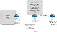
Now I changed the IOS of R1 to 12.4 15 T1 and was able to serve internet to esteemed customers. Below are the findings after adding 12.4 15T1 to R1
Results of CE Ping
CE# ping 4.2.2.2 source loopback 0
Sending 5, 100-byte ICMP Echos to 4.2.2.2, timeout is 2 seconds:
Packet sent with a source address of 3.1.1.1
!!!!!
Success rate is 100 percent (5/5)
INTERNET_MPLS# show ip bgp vpnv4 vrf CUST
Network Next Hop Metric LocPrf Weight Path
Route Distinguisher: 1:1 (default for vrf CUST)
*> 0.0.0.0 1.1.1.1 0 32768 i
*> 2.2.2.0/30 0.0.0.0 0 32768 ?
INTERNET_MPLS#sh mpls forwarding-table vrf CUST 0.0.0.0 0
Local Outgoing Prefix Bytes tag Outgoing Next Hop
tag tag or VC or Tunnel Id switched interface
None Untagged 0.0.0.0/0 0 Fa0/0 1.1.1.1
Findings After Adding 12.2 31 SB13a) If the same router is advertising a default route and customers vrf are coming onto the same router in that case SB 13 is not able to serve internet to customers.
b) If default route is leaked in customer vrf then customer is able to surf internet.
c) If the default route is announced on another router except SB13, In that case internet works fine. See Figure 3
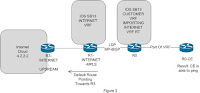
What My Thought Process Says
SB13 is not able to convert vpn traffic to ip traffic on the same router. Because in my scenario customer is forwarding ip traffic and R1 is receiving in the vrf and on the same router it converts the vpnv4 traffic to ip traffic and consequence customer is not able to surf internet. But if the default route shifted to another PE and SB13 route forwards the VPNv4 traffic till that router and thereafter traffic is converted to ip traffic and everything works fine.
Workaround
Either change the IOS or shift the default route to somewhere else so that till that VPN label will be swapped and thereafter traffic will be converted to ip traffic.
regards
shivlu jain
Click Here To Read Rest Of The Post...
Subscribe to:
Posts (Atom)